Faculty
Dr. Mohamed Soliman
Professor of Petroleum Engineering
Experimental Set-Up
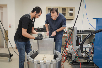
A pulse plasma generation equipment was designed with the output capacity of up to 20 kJ of electrical energy. The equipment consists of three major components: an electrical component, a true tri-axial cell, and a monitoring and recording system. The following sections describe different pieces of the equipment, the geometry of the rock samples, the experiment results, and discussion.
Electrical Component
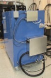
The electrical unit (Figure 1a) is responsible for storing and releasing electrical energy. It houses the high voltage charging system, capacitors, and the spark-gap switch. The electrical energy is stored in two 40 kV capacitors of 12.5 µF capacitance (Figure 1b). The charging energy is provided by a high capacity/high ramping rate high voltage supply. A spark-gap switch provides a mechanism of triggering the discharge. The threshold voltage in the spark-gap switch is controlled by air pressure, and discharge occurs through a secondary Marx generator to initiate arc formation. The stored electrical energy in capacitors is transferred to the wellbore using three high-voltage cables (Figure 1c) from the top of the triaxial cell. The cables are connected to two parallel and insulated copper rods (Figure 1d) through which the depth at which pulse discharge occurs is controlled. At the end of the two rods, a metal wire (Aluminum in this study) is attached to serve as a fusible link. The high voltage causes the link to vaporize and give rise to plasma generation and shockwave expansion. The sudden expansion provides the mechanical energy for generating multiple fractures in the test sample.
 (a)
(a)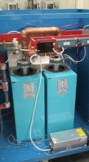 (b)
(b)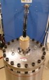 (c)
(c)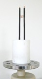 (d)
(d)Figure 1. Electrical component: (a) container cabinet (b) capacitors and spark gap (c) High voltage cables are connected to the cell from top (d) electrodes and fusible link
Triaxial Cell
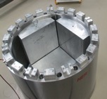
The triaxial cell houses the sample and provides the mechanism for applying the three principal stresses on the sample. Figure 2a shows the inside of the cell and metal plates that apply the confining stresses. The cell has three fixed plates (two on the sides and one on the top), and two of them are shown in Figure 2a. The stresses are applied by hydraulic actuators (Figure 2b). The triaxial cell has an opening from the top for lowering the electrodes. The sample is lowered and placed inside the cell, and other plates are placed around it (Figure 2c). The maximum sample dimensions that can be fit in the cell are 14”x14”x14”.
 (a)
(a)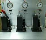 (b)
(b)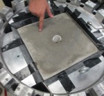 (c)
(c)Figure 2. Triaxial cell (a) Tri-axial cell with hydraulic pumps (b) two fixed plates on the sides and the vertical actuator on the bottom (c) sample and all horizontal plates on the sides.
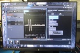
Monitoring and Recording System
Monitoring and recording system (Figure 3) consists of fast pressure gauges, electronic oscilloscopes, remote triggering mechanisms, and a computer for gathering data from the scopes.
 (a)
(a)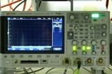 (b)
(b)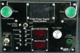 (c)
(c)Figure 3. Monitoring and recording system (a) Keysight Benchvue software (b) oscilloscope (c) remote triggering.